Go Back   XmodSource.com > Xmods > XMOD Electronics
Register FAQ Members List Calendar Gallery iTrader Today's Posts

Reply
 
Thread Tools Display Modes
  #1  
Old 01-18-2009, 11:15 AM
xzc426's Avatar
xzc426 xzc426 is offline
Stage 2 member
 
Join Date: Mar 2008
Location: TX
Posts: 99
Trader Rating: (1)
Default Fried fet stacking

I have one fried fet (forward fet) and I was wondering if it was possible to stack fets without removing any of them. So I would have two good fets on reverse, and one fried and one good on forward. Would that work? Thanks.
Reply With Quote
  #2  
Old 01-18-2009, 11:19 AM
civicblack10's Avatar
civicblack10 civicblack10 is offline
Elite member
 
Join Date: Dec 2006
Location: spooner street
Posts: 542
Trader Rating: (8)
Default

That would work for the reverse since the reverse fet isnt fried, but the front one has to be removed.
Reply With Quote
  #3  
Old 01-18-2009, 11:21 AM
xzc426's Avatar
xzc426 xzc426 is offline
Stage 2 member
 
Join Date: Mar 2008
Location: TX
Posts: 99
Trader Rating: (1)
Default

Ok, so then I can have 2 on reverse and 1 on forward if I remove the fried one?
Reply With Quote
  #4  
Old 01-18-2009, 12:21 PM
lol lol is offline
Banned
 
Join Date: Jun 2007
Posts: 1,001
Trader Rating: (14)
Default

Quote:
Originally Posted by blt456 View Post
FETS 101

Part 1
**Fet- Field effect transistor
**MOSFET- upgraded fet, less internal resistance/ more amp capacity to be drawn

Questions and Answers:

--How high should I stack my fets?--

*** Depends on: motor, batteries, chassis, and how smooth of a car you want. You can do a silly 2x10 mosfet stack, and have it be very unsmooth, more fets lead to very unsmooth, driving cars and truck. Using the minimum amount of fets for a motor allows (most of the time) smoother power delivery, but higher chances of frying fets and stacks. An advantage to higher stacks is that they allow the motor to go to its full potential, total spin up, so it can achieve what is claimed. Smaller/ minimum stacks do not allow this, but key to racing circuit is about usable power. *** So, in a short summary:
**Go high for dyno queens, show cars, and speed runners
**Low for usable power, track racing

--Should I get a Woah Nelly, Spider or AM v2.2/v2.1:--

***I have heard mixed opinions about the v2.2, nelly, and spider. Nelly is no longer in production, with that aside, AM vs. Spider.
The AM v2 regulated board has it’s pros and cons, I myself have not tried one, but from research, opinions of skilled modders, they seem to dislike this board, from fets lifting off pads to inefficiency, and room.
I myself have had two spider v3.0s, and loved both. Work great, have fair amount of internal resistance (a LOT less than the v2.2, key is smaller fets for usable power, v2.2 is for dyno queens only). Only downside is removing stock fets, but that is not hard for a modder with a bit of knowledge, or skill. ***


Tips on removing stock fets:

--Ph2t’s method (I use it, and only will); basically cutting the fet legs with a hobby knife, instead of having any heat involved. This is a tad dangerous, as if the knife slips… (happened a few times, and made a mess)

--Regular method; Use desolder braid to remove the solder pre-applied, to the fets legs can be moved to lift off. I do not follow this method in any way, as ripping pads off is very easy while doing this (when solder turns solid, and a strand of braid is connected, when lifted, it can life a pad).

--Fixing lifted pads:
Basically, to fix lifted fet pads, you need some sort of jumper wire (stock potentiometer/servo motor wires would be best), and solder. You must locate board traces from the pin(s) of the pads that had been ripped/lifted, and locate their trace(s). You then tin the jumper wire, solder it to the corresponding fet legs, and solder it to the trace. This is not the easiest method, but after being soldered, I would do a test, and if it works, put some sort of glue over the solder point on the trace (dot of crazy glue, hot glue, etc..) so it doesn’t rip off.


Part 2

--Mosfets compatible with gen1 xmod: Vishay 4562, 8962, 8858, IRF7317, IRF7314, FDS8858CZ, and sp8m4 (8858cz is cheapest, and is almost equivalent to sp8m4 due to rds values on N channel, a tad more than sp8m4, but P channel cannot carry as many amps)

--Mosfets for Micro-t: Most of the above listed should work

--Mini-z: Same as above.

**Disclaimer: Some fets may not work, but based upon research input/output pins seem to be the same ***

*Typical data sheet for a mosfet (link is for 8858cz by Fairchild Semi)

http://www.fairchildsemi.com/ds/FD/FDS8858CZ.pdf


Internal resistance:
When you upgrade fets, your car/truck’s performance gains (most of the time), increase. The increasing gains can surpass others from many aspects, such as solder work, and internal resistance of the mosfets themselves. Internal resistance plays a MAJOR role in a smooth, linear, power-delivering vehicle. Some actually prefer fets with lots of internal resistance, and use higher stacks, as they like the “feel” of them better than others when driving.

Power hungry car and trucks will clearly require more fets upon chassis upgrades, motor and battery install. The more resistance, the more prone your boards are to frying the fets. With generation1, I would recommend the 8858cz by Fairchild Semi, or the SP8M4, as they have the least internal resistance, and when compared, are equal. (In the sense of amp draw/internal resistance)

From BLT's FAQ.
Reply With Quote
  #5  
Old 01-18-2009, 05:16 PM
xzc426's Avatar
xzc426 xzc426 is offline
Stage 2 member
 
Join Date: Mar 2008
Location: TX
Posts: 99
Trader Rating: (1)
Default

Quote:
Originally Posted by AzNKevin4EvA View Post
From BLT's FAQ.
....yes, I read it before posting. I didn't see the answer to my question though. ...or was that just me
Reply With Quote
  #6  
Old 01-18-2009, 05:22 PM
SUPERSHELBY's Avatar
SUPERSHELBY SUPERSHELBY is offline
The Original S.S.
 
Join Date: Feb 2007
Location: Sooner State
Posts: 960
Trader Rating: (2)
Send a message via AIM to SUPERSHELBY Send a message via Yahoo to SUPERSHELBY
Default

u can stack them without removing them but u should a signifigant gain in anything, but itd be better if u just purchase all new FETs
__________________
"The Mustang's enormous success inspired Chevrolet and Dodge to create their own retro-styled muscle cars in the form of the new Camaro and Challenger."

Reply With Quote
  #7  
Old 01-19-2009, 12:14 AM
XMDrifter's Avatar
XMDrifter XMDrifter is offline
drifter and engineer
 
Join Date: Jul 2006
Location: St Louis
Posts: 2,179
Trader Rating: (5)
Send a message via AIM to XMDrifter
Default

you technically do not need to remove the old fets. removing them just looks neater. fet removing is the most frustrating thing ever, so i prefer just to stack on them if i have a 2x1 kit. if i have a 2x2 kit, then it's a different story...makes it easier.
but anyways, no you do not have to remove them.
it looks nicer, but it does no harm leaving the old fets there. (unles you completely fry a big stack, then you should remove them to keep an excess of bulk from building up)
__________________
Reply With Quote
  #8  
Old 01-20-2009, 08:29 PM
xzc426's Avatar
xzc426 xzc426 is offline
Stage 2 member
 
Join Date: Mar 2008
Location: TX
Posts: 99
Trader Rating: (1)
Default

#@$%&*!!!! Ok, so I got the fets I ordered on atomic (these http://www.atomicmods.com/ZoomImage....roductID=10578) and I took the old one off and soldered the new one in (the 7324). It's facing the right way and none of the pins are touching where they're not suppose to be, but it still doesn't run forward. The 7324 is the forward FET right? Perhaps something other than my FET is broken, or I fried my new FET too? If anything it's probably the latter......unless I replaced the wrong one. help save my car

PS: are FETs easy to fry? I made sure I didn't touch the black with my soldering iron and not to have the iron on the pins for too long......

Update: Ok, I replaced the other fet too. It seems like it's not an issue with the FETs because I was able to replace the reverse FET successfully. It doesn't guarantee that I didn't fry the forward fet, but it gives some ground to assume that I didn't. None of the solder is touching anything other than the pins they're suppose to be touching. I've also double checked that the FETs are facing the right direction. So assuming that both the FETs work, what would I need to check? I've checked the controller and I didn't see anything that seemed unusual to me, and the servo works fine...anything else I should take a look at? I haven't discarded the possibility that my solder work is faulty so here's some pics of the FETs that I put in.


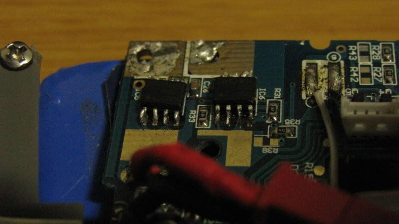
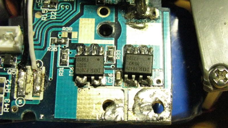
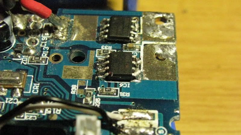
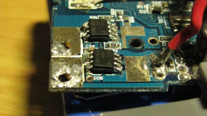
Last edited by xzc426; 01-21-2009 at 01:12 AM..
Reply With Quote
  #9  
Old 01-21-2009, 03:29 PM
vietnamezerice vietnamezerice is offline
Stage 2 member
 
Join Date: Jan 2009
Posts: 63
Trader Rating: (1)
Default

looks good to me!
Reply With Quote
  #10  
Old 01-21-2009, 07:12 PM
xzc426's Avatar
xzc426 xzc426 is offline
Stage 2 member
 
Join Date: Mar 2008
Location: TX
Posts: 99
Trader Rating: (1)
Default

Quote:
Originally Posted by vietnamezerice View Post
looks good to me!
looks good, but it doesn't run

PS: the 7324 is the forward fet right?
__________________
------------------------------------------------------------------------------------------------------


Quote:
Originally Posted by ---------- View Post
yea thats true, cm or mm its still 8.4
lol ^^^^^^^^

Last edited by xzc426; 01-21-2009 at 07:46 PM..
Reply With Quote
  #11  
Old 01-21-2009, 10:07 PM
XMDrifter's Avatar
XMDrifter XMDrifter is offline
drifter and engineer
 
Join Date: Jul 2006
Location: St Louis
Posts: 2,179
Trader Rating: (5)
Send a message via AIM to XMDrifter
Default

the orientation is correct, so i'm assuming that it might have fried during installation.
how long did you hold the iron to it?
__________________
Reply With Quote
  #12  
Old 01-21-2009, 10:51 PM
xzc426's Avatar
xzc426 xzc426 is offline
Stage 2 member
 
Join Date: Mar 2008
Location: TX
Posts: 99
Trader Rating: (1)
Default

Quote:
Originally Posted by XMDrifter View Post
the orientation is correct, so i'm assuming that it might have fried during installation.
how long did you hold the iron to it?
I'd say no more than a second for each of the individual pins and maybe 2 seconds or less for the double pins.
__________________
------------------------------------------------------------------------------------------------------


Quote:
Originally Posted by ---------- View Post
yea thats true, cm or mm its still 8.4
lol ^^^^^^^^
Reply With Quote
  #13  
Old 01-21-2009, 11:38 PM
vietnamezerice vietnamezerice is offline
Stage 2 member
 
Join Date: Jan 2009
Posts: 63
Trader Rating: (1)
Default

i believe the 9910's are the forward fets
Reply With Quote
  #14  
Old 01-22-2009, 05:29 PM
XMDrifter's Avatar
XMDrifter XMDrifter is offline
drifter and engineer
 
Join Date: Jul 2006
Location: St Louis
Posts: 2,179
Trader Rating: (5)
Send a message via AIM to XMDrifter
Default

the 9910's go in front of the other fets.
your orientation is right
__________________
Reply With Quote
Reply


Currently Active Users Viewing This Thread: 1 (0 members and 1 guests)
 

Posting Rules
You may not post new threads
You may not post replies
You may not post attachments
You may not edit your posts

BB code is On
Smilies are On
[IMG] code is On
HTML code is Off

Forum Jump


All times are GMT -4. The time now is 11:45 PM.


Powered by vBulletin® Version 3.8.7
Copyright ©2000 - 2024, vBulletin Solutions, Inc.